Nandpro - Could Not Detect Flash Controller

one thing I did notice.

When I'm testing the wires....I have the multimeter set to 200ohms.

On the ones with resistors attached the reading would be about 100-102ohms which is fine.

On the ones without the reading is something like 1 or 2 or whatever (constantly moving - but same as when I try touching the 2 multimeters together)

Now on the switching diode...I dont seem to get a reading from that one. At first I thought I'd broken the diode and grabbed a new one from the pack...but tested the diode either side before soldering anything and it didnt give any readings (but once in while at random seemed to get a reading which would go shortly after?)....whats the best way/setting to test the switching diodes are ok?
 
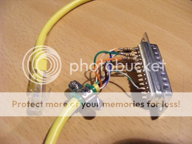
Your plug should be wired like this mate. Ignore the fact that this is a RJ45/patch cable. The important part is the way the lpt plug is wired.
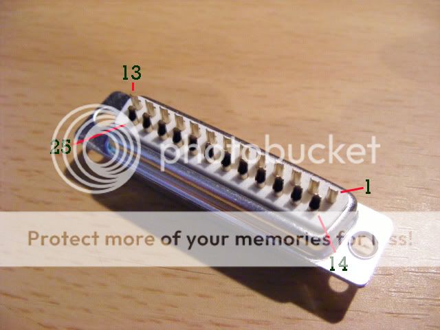
This is a back view of the lpt plug. You can easily see where pin 11 is there (the one on its own)
DSCF8085.jpg

DSCF8111.jpg


Also im afraid your solder does look a bit ropey lol - And im so bad too. But dont dispare. You will get there. Just clean things up and take your time. There are plenty soldering guides/videos on youtube that will help. Twist the ends of your cable, then "Tin" them with solder, Then make a tiny blob of solder on each point. This along with the "Tinning" of your lpt cable will help you achieve a good solid connection. Personally I pulled each of my cables as I attached them just to double check the connection was solid and secure.
Like I said before on here I think im the worst solderer in the world, But I just took my time mate. There is no point in rushing it. A nice bright light and one of them hands free magnifying glasses is what I used.......I am pretty blind though lol so i needed the magnifier. Take a break if your getting fustrated and it will seem easier in the morning.
 
XP on both pcs mate....and yup port95 installed
right let's see if we can get this going ok your running xp you have your port sorted right you chopped a printer cable yes??? do you have a multi meter??
 
work with me dude ive just stripped a 360 down in the effort of helping you out
 
Your plug should be wired like this mate. Ignore the fact that this is a RJ45/patch cable. The important part is the way the lpt plug is wired.
This is a back view of the lpt plug. You can easily see where pin 11 is there (the one on its own)
DSCF8085.jpg

DSCF8111.jpg


Also im afraid your solder does look a bit ropey lol - And im so bad too. But dont dispare. You will get there. Just clean things up and take your time. There are plenty soldering guides/videos on youtube that will help. Twist the ends of your cable, then "Tin" them with solder, Then make a tiny blob of solder on each point. This along with the "Tinning" of your lpt cable will help you achieve a good solid connection. Personally I pulled each of my cables as I attached them just to double check the connection was solid and secure.
Like I said before on here I think im the worst solderer in the world, But I just took my time mate. There is no point in rushing it. A nice bright light and one of them hands free magnifying glasses is what I used.......I am pretty blind though lol so i needed the magnifier. Take a break if your getting fustrated and it will seem easier in the morning.

a fecking hell!!! Looks like it IS the wrong way round!!

This is the pic I used

wiringforxenondiagramre.jpg


And if you look on there.....the pic looks like the pinouts that go to the pc. ALSO....on the left you can see a screw that is pointing away from the camera!! That says to me that its the other way around by my looking at it? In fact cos I saw that "screw" I thought it MUST be that way :FRIGHT:
 
work with me dude ive just stripped a 360 down in the effort of helping you out

Hiya pil196.

See my above post!!! grrrrrrr can't fookin believe it!!

Right - I've just set up a laptop downstairs (been running upstairs each time to net pc)...so I can update the page.

I'm just going to snip off an lpt end and resolder it the CORRECT way!!!

Please tell me its not just me that the other pic I used is confusing/misleading

edit - oh hang on no.....it DOES look the same way.....errr hang on let me check this wiring!!!
 
Oh man.!!! I'm such a dick!!! I actually acknowledged the way correctly in the pic.....but when it came to me soldering the bloody thing I still looked at it the wrong way round


arrggggghhhh

right - snipping new cable - best put them resistors back on too
 
a fecking hell!!! Looks like it IS the wrong way round!!

This is the pic I used

wiringforxenondiagramre.jpg


And if you look on there.....the pic looks like the pinouts that go to the pc. ALSO....on the left you can see a screw that is pointing away from the camera!! That says to me that its the other way around by my looking at it? In fact cos I saw that "screw" I thought it MUST be that way :FRIGHT:

if you look inside your db25 socket it will have numbers first row 1 to 13 second row 14 to 25 solder the 100 om resisters to pins 1, 2, 14 on the db25 plug have you done this??
 
yup db25 opened - no numbers as such printed on tho - tho it is a premade printer cable I pinched from work just waiting for solder iron to heat up again so can take old wires off and attach existing ones.

I defo put them on wrong way round....can't believe I did that....and looked at it several times too to double check!!!!

right when its heated up solder your resistors 5 0f them 100om looking at the plug from the back top row from right to left
. . . . . . . . . . . . .
. . . . . . . . . . . .
solder a resistor to pin one top line first one on the right and another to pin 2 and another to pi 14 thats the one on the bottom line first one now staying on the bottom line another one to pin 16 and 17 whilst your at it soldr a wire to pin 18 that will be your ground for the other ground wires from the board.
 
speed it up bud after watching that video you should be a expert by now lol

if your unsure of the pins use a multi meter on continuity test to See what pin corresponds to what wire
 
Last edited:
Hmmm er what can I say.....glad to have helped out. Atleast there has baan no harm done mate. Just a bit of time down the drain but no real damage as such. Remember dont rush it or you could end up in an even worse mood.:Fish:
 
well after seeing the pins wrong way round - cheered up bit more cos at least I have a bit of hope lol

last of pins are in lpt now - just about to reconnect other pc and try running....heres hoping!!!
 
well after seeing the pins wrong way round - cheered up bit more cos at least I have a bit of hope lol

last of pins are in lpt now - just about to reconnect other pc and try running....heres hoping!!!
let us know m8
 
forgot to solder an earth wire from lpt port to 360 chassis (recommended form earlier readong) - so just quickly done that - right - setup pc!!! grrr need more working space
 
forgot to solder an earth wire from lpt port to 360 chassis (recommended form earlier readong) - so just quickly done that - right - setup pc!!! grrr need more working space
believe it or not the earth points can play a big part in errors
 
believe it or not the earth points can play a big part in errors

ya mean as in I should remove it? did get a lil shock from the bugger when the earth point hit my arm like by mistake

pc booting now!!! 360 wont turn on when lpt is connected when trying out of curiosity.....dont know if thats a good thing or not
 
yayyyyyyyyyyyyyyyyyy it's reading!!!!!!! what a big donkey's co**k I am!! all these hours!!!

Just got it doing the -r3 to check the CB ver first as per another guide - dunno how long that will take tho (Xenon)

Think I better make plenty dumps of full rom to make sure accurate considering my shit wiring!! In its current state defo know I can't keep it on cos its brittle as anything (and didnt trim enough of the diode metal either side off nor resistor so way too bulky......thank god that once its on ya can now flash from within the 360

Thanks all;....I could kiss you and make sweet love in all rooms of the house (except toilet cos I stunk it out earlier!!)
 
ya mean as in I should remove it? did get a lil shock from the bugger when the earth point hit my arm like by mistake

pc booting now!!! 360 wont turn on when lpt is connected when trying out of curiosity.....dont know if thats a good thing or not
to be honest m8 i don't turn on the 360 just plug the power in but i have heard that some do turn on the power but the 360 powers up any chance you can post up some pics of what you have done so far. also forget about the smc jtag at this point
 
while doing this

"nandpro lpt: -r3 -c1.bin"

It so far has found 1 bad block

Error: 250 Reading Block 5d

Would I be right in thinking that when just getting the cb section of the nand it should not have any bad blocks? or could it have them too?
 
Back
Top