Midnight Tboy
Inactive User
- Joined
- Feb 23, 2008
- Messages
- 851
- Reaction score
- 7
Yellos.
ok so I'm doing my first jtag attempt
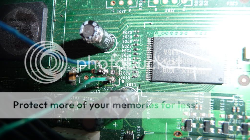
Being a noob at soldering - it took forever and a day (well ok a few hours) to get the wires etc soldered together...and had nightmare time trying to get them on the board but eventually got there.
The connections 'seem' to be fine, testing with a multimeter and can't spot any shorts.
This is using 5x100ohms on the cable, and also including the 1n4148 switching diode. I have not put the other 3 cables on as I read that is not needed until the point after the nand has been backed up.
However on Nandpro, when running, it scans 3 ports, then I get "Could Not Detect Flash Controller"
argghhhh
Power is connected to 360 btw....switched on at plug socket - but not actually turning the 360 on..
I've tried with brand new pcs with fresh XP image, and also on a trusty ancient xbox-flasher pc with the same issue.
Again rechecking my soldering and it seems ok.
Any ideas what I can do?
The 360 powers up when the lpt cable is not plugged in, and refuses to power on when its connected to the pc which I've read is what should happen (no brick light change however - just stays amber?)
I've searched a bit and someone mentioned trying taking the 100ohm resistors off which worked for them....followed by others saying if you do and it sends a 5v down the lpt then it most likely will fry the 360 eek.
Should I even attempt that? Whats best way to tell if getting the 5v down the lpt to see if I could do that? (presume with multimeter but not sure what settings)
Also should I try taking the switching diode off (It is the correct way with the Black line facing the motherboard btw) or will that be pointless?
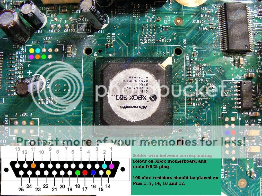
I'm working from this pic btw in effect
http://img44.imageshack.us/img44/7332/wiringforxenondiagramre.jpg
and looking at the pic I have based "pin 1" on the lpt as being "on the photo of it it shows the side where you connect to the lpt (because the screws are facing other way), and so therefore in effect when soldering the layout is mirrored - so facing the lpt when soldering = pin 1 on top left
Also I have the tried the lpt mode in ECP, EPP, and ECP+EPP, also with a couple of different addresss
ok so I'm doing my first jtag attempt
Being a noob at soldering - it took forever and a day (well ok a few hours) to get the wires etc soldered together...and had nightmare time trying to get them on the board but eventually got there.
The connections 'seem' to be fine, testing with a multimeter and can't spot any shorts.
This is using 5x100ohms on the cable, and also including the 1n4148 switching diode. I have not put the other 3 cables on as I read that is not needed until the point after the nand has been backed up.
However on Nandpro, when running, it scans 3 ports, then I get "Could Not Detect Flash Controller"
argghhhh
Power is connected to 360 btw....switched on at plug socket - but not actually turning the 360 on..
I've tried with brand new pcs with fresh XP image, and also on a trusty ancient xbox-flasher pc with the same issue.
Again rechecking my soldering and it seems ok.
Any ideas what I can do?
The 360 powers up when the lpt cable is not plugged in, and refuses to power on when its connected to the pc which I've read is what should happen (no brick light change however - just stays amber?)
I've searched a bit and someone mentioned trying taking the 100ohm resistors off which worked for them....followed by others saying if you do and it sends a 5v down the lpt then it most likely will fry the 360 eek.
Should I even attempt that? Whats best way to tell if getting the 5v down the lpt to see if I could do that? (presume with multimeter but not sure what settings)
Also should I try taking the switching diode off (It is the correct way with the Black line facing the motherboard btw) or will that be pointless?
I'm working from this pic btw in effect
http://img44.imageshack.us/img44/7332/wiringforxenondiagramre.jpg
and looking at the pic I have based "pin 1" on the lpt as being "on the photo of it it shows the side where you connect to the lpt (because the screws are facing other way), and so therefore in effect when soldering the layout is mirrored - so facing the lpt when soldering = pin 1 on top left
Also I have the tried the lpt mode in ECP, EPP, and ECP+EPP, also with a couple of different addresss
Last edited:
")