I am sure they are both black at one end of the band ,but not 100% about then middle bands because of scorching.
I get the same readings when i reverse the probes.
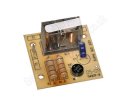
The blue cap says R4D 63V 10UF 85 celcius.
I could have a go at soldering,i have the gear but not much idea really,worth a try though,where is the best place to get the parts from?
would you just replace the 2 resistors?
We're both typing at the same time.
")
Assuming the relay coil checks ok (mutimeter) I'd be inclined to change everything else, very little cost.
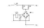
It would take longer to explain how to test the bridge, than to change it.
We need to find out, (or make an educated guess depending on relay coil voltage/resistance) what the resistor values were.
After that, just take the board to your local Maplin store (or similar ) for parts, or I can post if you have the time.
Alternatively, you can post the pcb to me, will change and return, again if you have time.
You'll need a soldering iron with a 5mm bit or smaller, suggest practice on any old pcb you can find.