Introduction
Ethernet has undergone a number of transformations over the years but it can still be worth looking at some of the earlier incarnations as rules from the past have a habit of popping up and nipping us if we are not careful.
Of course, there have been other networking technologies over the years, many of which have come and gone. Some do remain but in reality most people, both at home and in work, will never see them as they are very much in the minority.
Thick Ethernet (10base5)
The earliest commercial implementation of Ethernet was known as Thick Ethernet or 10base5. The name 10base5 is derived from the specification, 10 represents the speed in Mbps, base refers to the fact that it's a baseband technology while the 5 refers to the maximum segment (individual cable) length in 100's of metres.
The easiest way to think of baseband is that there is just a single signal on the line, in this case Ethernet. With broadband you have more than one signal i.e. Internet and 'phone, both can be used simultaneously.
Thick Ethernet is so-named because the cable is thick. It's similar to garden hosepipe and a tasteful shade of yellow.
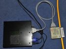
In the picture above the yellow cable is Thick Ethernet. It's a coaxial cable and devices are connected via a vampire tap which, as its name suggests, made use of spikes to make contact with both the central conductor and the outer shield. A hole was drilled (using a depth gauge) through to the central conductor . A transceiver is connected to the vampire tap and a flexible cable (AUI cable) is used to connect to the device.
Thick Ether is somewhat heavy, unwieldy and can be damaged if too tight a bend radius is used so it wasn't really suitable for general LAN cabling.
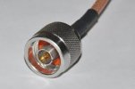
N-type connector as used in 10base5 networks.
Thin Ethernet (10base2)
Thin Ethernet (Thinnet) uses a lighter coaxial cable similar to TV coax which is flexible enough to connect directly to desktop devices. The name 10base2 is derived in a similar manner to 10base5 but in this case a maximum segment length of 200 metres is allowed.
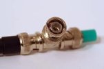
Connections are via BNC connectors like the one above. A BNC T-piece is connected to one end of the cable, the centre is connected to the device and the remaining connection is to the next device or terminated as above (the connector with the green tip).
Coaxial cables need to be terminated at each end, if they are left open signal degradation occurs.
Neither Thick or Thin Ethernet are much in evidence these days having been superceded. The rules, however, are a different matter.
Ethernet Rules
One of the simplest to remember is the 5-4-3 rule which specifies a maximum of 5 segments connected by 4 repeaters with devices connected to just 3 of the segments.
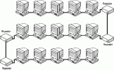
Given the maximum number of segments is 5 it follows that Thick Ethernet can have a maximum length of 2500m while Thin Ethernet is limited to 1000m.
Segment ends are always terminated with a 50 ohm impedance, BNC for Thin Ethernet and N-type for Thick Ethernet.
Ethernet Today (10baseT and beyond)
One issue with both coaxial cable types was the expense of cabling a building and having to leave it all behind if the organisation moved. This led to the development of Ethernet over twisted pair, a cheaper cable similar to that used in telephone systems. In fact, the original specification anticipated the use of existing voice cabling systems. Unshielded with 4 twisted pairs, this cable provides for 2 pairs for 10baseT which leaves 2 pairs for other uses such as 'phone connection.
However, given the cost of the cable and the fact that some later Ethernet standards required all 4 pairs it is more usual to use separate cable runs for 'phone and computer. The name 10baseT is derived in a similar way 10base5 and 10base2 with the T referring to Twisted pair.
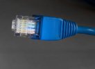
RJ45 connector as used in 10baseT cabling systems.
Category 3 (or Cat 3) cable was used initially and is still used in many voice installations but, as network speeds increased, a higher specification cable was required. Cat3 is fine for 10Mbps but for 100Mbps you would need Cat 5 or Cat5e while for Gigabit Ethernet Cat 6 is required for maximum performance.
Apart from the stamping on the sheath all these cables look very similar so it is important to check that different specifications of cable are not mixed. Be aware that the twists are to reduce crosstalk between channels so, when making connections, untwist as little as possible.
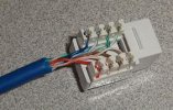
Connections to sockets and patchpanels are made using a Krone tool and results will be similar to the picture above although a little less sheath removed would have been better.
Wall points are wired back to a patchpanel in the computer room as the picture below illustrates.
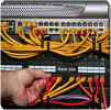
The box at the top is a switch while the patchpanel is shown underneath. Patch cables are used to connect the switch to the patchpanel thus making the wall point 'live'. Usually, colour-coded patch leads are used to indicate the type of device being connected.
Maximum cable lengths are nominally 100m and it is usual to run up to 90m of solid-core leaving a maximum of 10m of flexible fly-lead to accommodate connection from wall socket to device and patch leads at the other end of the cable. Unlike coaxial Ethernet which has a bus topology (the 'shape' of the network), twisted pair Ethernet uses a star topology.
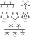
In bus topologies the cable runs from device to device whereas in a star topology the cables run back to one or more central devices. In early implementations of 10baseT, hubs were used as the central device. Hubs are simply repeaters with numerous ports i.e.
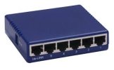
Above is a 5-port hub, the 6th port is known as the uplink port i.e. you can connect another hub to extend the network. However, remember it's still a repeater so you can only cascade to a maximum of 4.
Current networks use switches rather than hubs to reduce the impact of collisions. As you can see from the picture below, they look very similar so it's important to be able to identify them. Replacing a switch with a hub will usually have a negative impact on network performance.
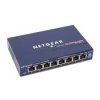
It's at this point that networks really start to develop because the use of hubs/repeaters prevent scaling beyond a few hundred devices whereas the use of switches allows thousands of devices. It's largely due to the lack of any form of intelligence in hubs/repeaters which simply retransmit any received datagrams on all of the other ports. This creates what is known as a single 'Collision Domain' or in other words every single device on the network can conflict with every other.
Switches create multiple collision domains, one per device, by switching traffic so that it is sent only to the required destination(s). To understand this it's necessary to understand how datagrams get from one device to another and, ultimately, this is by MAC address. The datagram contains both MAC addresses i.e. source and destination.
Whereas a hub would send this datagram to all devices, the switch builds a map of MAC addresses so it knows which port the source and destination MAC addresses are connected to. Unnecessary network traffic is reduced because it is sent only to device(s) that are 'interested'. This ability to make use of MAC addresses makes these first switches Layer II devices in terms of the OSI 7-layer model. Layer II switches fall back to Layer I operation where a MAC address is not in the map i.e. they act like repeaters.
Switching technology and higher transmission rates (100Mbps, 1000Mbps etc) are significant in making larger modern networks possible. However, without suitable protocols, traffic is still confined to the Local Area Network (LAN).
Ethernet has undergone a number of transformations over the years but it can still be worth looking at some of the earlier incarnations as rules from the past have a habit of popping up and nipping us if we are not careful.
Of course, there have been other networking technologies over the years, many of which have come and gone. Some do remain but in reality most people, both at home and in work, will never see them as they are very much in the minority.
Thick Ethernet (10base5)
The earliest commercial implementation of Ethernet was known as Thick Ethernet or 10base5. The name 10base5 is derived from the specification, 10 represents the speed in Mbps, base refers to the fact that it's a baseband technology while the 5 refers to the maximum segment (individual cable) length in 100's of metres.
The easiest way to think of baseband is that there is just a single signal on the line, in this case Ethernet. With broadband you have more than one signal i.e. Internet and 'phone, both can be used simultaneously.
Thick Ethernet is so-named because the cable is thick. It's similar to garden hosepipe and a tasteful shade of yellow.

In the picture above the yellow cable is Thick Ethernet. It's a coaxial cable and devices are connected via a vampire tap which, as its name suggests, made use of spikes to make contact with both the central conductor and the outer shield. A hole was drilled (using a depth gauge) through to the central conductor . A transceiver is connected to the vampire tap and a flexible cable (AUI cable) is used to connect to the device.
Thick Ether is somewhat heavy, unwieldy and can be damaged if too tight a bend radius is used so it wasn't really suitable for general LAN cabling.

N-type connector as used in 10base5 networks.
Thin Ethernet (10base2)
Thin Ethernet (Thinnet) uses a lighter coaxial cable similar to TV coax which is flexible enough to connect directly to desktop devices. The name 10base2 is derived in a similar manner to 10base5 but in this case a maximum segment length of 200 metres is allowed.

Connections are via BNC connectors like the one above. A BNC T-piece is connected to one end of the cable, the centre is connected to the device and the remaining connection is to the next device or terminated as above (the connector with the green tip).
Coaxial cables need to be terminated at each end, if they are left open signal degradation occurs.
Neither Thick or Thin Ethernet are much in evidence these days having been superceded. The rules, however, are a different matter.
Ethernet Rules
One of the simplest to remember is the 5-4-3 rule which specifies a maximum of 5 segments connected by 4 repeaters with devices connected to just 3 of the segments.

Given the maximum number of segments is 5 it follows that Thick Ethernet can have a maximum length of 2500m while Thin Ethernet is limited to 1000m.
Segment ends are always terminated with a 50 ohm impedance, BNC for Thin Ethernet and N-type for Thick Ethernet.
Ethernet Today (10baseT and beyond)
One issue with both coaxial cable types was the expense of cabling a building and having to leave it all behind if the organisation moved. This led to the development of Ethernet over twisted pair, a cheaper cable similar to that used in telephone systems. In fact, the original specification anticipated the use of existing voice cabling systems. Unshielded with 4 twisted pairs, this cable provides for 2 pairs for 10baseT which leaves 2 pairs for other uses such as 'phone connection.
However, given the cost of the cable and the fact that some later Ethernet standards required all 4 pairs it is more usual to use separate cable runs for 'phone and computer. The name 10baseT is derived in a similar way 10base5 and 10base2 with the T referring to Twisted pair.

RJ45 connector as used in 10baseT cabling systems.
Category 3 (or Cat 3) cable was used initially and is still used in many voice installations but, as network speeds increased, a higher specification cable was required. Cat3 is fine for 10Mbps but for 100Mbps you would need Cat 5 or Cat5e while for Gigabit Ethernet Cat 6 is required for maximum performance.
Apart from the stamping on the sheath all these cables look very similar so it is important to check that different specifications of cable are not mixed. Be aware that the twists are to reduce crosstalk between channels so, when making connections, untwist as little as possible.

Connections to sockets and patchpanels are made using a Krone tool and results will be similar to the picture above although a little less sheath removed would have been better.
Wall points are wired back to a patchpanel in the computer room as the picture below illustrates.

The box at the top is a switch while the patchpanel is shown underneath. Patch cables are used to connect the switch to the patchpanel thus making the wall point 'live'. Usually, colour-coded patch leads are used to indicate the type of device being connected.
Maximum cable lengths are nominally 100m and it is usual to run up to 90m of solid-core leaving a maximum of 10m of flexible fly-lead to accommodate connection from wall socket to device and patch leads at the other end of the cable. Unlike coaxial Ethernet which has a bus topology (the 'shape' of the network), twisted pair Ethernet uses a star topology.

In bus topologies the cable runs from device to device whereas in a star topology the cables run back to one or more central devices. In early implementations of 10baseT, hubs were used as the central device. Hubs are simply repeaters with numerous ports i.e.

Above is a 5-port hub, the 6th port is known as the uplink port i.e. you can connect another hub to extend the network. However, remember it's still a repeater so you can only cascade to a maximum of 4.
Current networks use switches rather than hubs to reduce the impact of collisions. As you can see from the picture below, they look very similar so it's important to be able to identify them. Replacing a switch with a hub will usually have a negative impact on network performance.

It's at this point that networks really start to develop because the use of hubs/repeaters prevent scaling beyond a few hundred devices whereas the use of switches allows thousands of devices. It's largely due to the lack of any form of intelligence in hubs/repeaters which simply retransmit any received datagrams on all of the other ports. This creates what is known as a single 'Collision Domain' or in other words every single device on the network can conflict with every other.
Switches create multiple collision domains, one per device, by switching traffic so that it is sent only to the required destination(s). To understand this it's necessary to understand how datagrams get from one device to another and, ultimately, this is by MAC address. The datagram contains both MAC addresses i.e. source and destination.
Whereas a hub would send this datagram to all devices, the switch builds a map of MAC addresses so it knows which port the source and destination MAC addresses are connected to. Unnecessary network traffic is reduced because it is sent only to device(s) that are 'interested'. This ability to make use of MAC addresses makes these first switches Layer II devices in terms of the OSI 7-layer model. Layer II switches fall back to Layer I operation where a MAC address is not in the map i.e. they act like repeaters.
Switching technology and higher transmission rates (100Mbps, 1000Mbps etc) are significant in making larger modern networks possible. However, without suitable protocols, traffic is still confined to the Local Area Network (LAN).
Last edited:
