TCP/IP - warts and all

Yep! You're right - I've been doing some tests with a M8 and pinned it down to some security options I applied some time ago...

I'm reluctant to relax these as they kill about 90,000 rubbish connections a month lol

The only thing I can suggest is installing a free SMTP service on your own system to test against. Then the example would be become:

Telnet to SMTP example:

Run up Telnet and connect to localhost (your PC) on port 25
A prompt should appear
Type helo engineer <ENTER> to get a 250 prompt
The session has been started
Type mail from:<[email protected]> <ENTER> to get 250 2.1.0 Ok (or similar)
You told the system this e-mail is from [email protected]
Type rcpt to:<[email protected]> <ENTER> to get 250 2.1.5 Ok (or similar)
You told the system to send the e-mail to [email protected]
Type data <ENTER> to get this prompt 354 End data with <CR><LF>.<CR><LF> (or similar)
Type a short message followed by <ENTER>, then a dot (.) then another <ENTER>
You'll get a message like this 250 2.0.0 Ok: queued as 27CAFC4A0D0
The number on the end changes each time
Finally type quit <ENTER>

Apologies - one of the joys of networking :)

If you try this, the link above has not been tested so please satisfy yourself it's clean. Alternatively you could possibly use your ISP SMTP server but then you would have to use your real e-mail address so don't do this if you prefer it not to be known :)
 
I think Win7 has a simple SMTP service in IIS. I'll try that.

EDIT - nope it seems to have been removed. :(
 
Last edited:
I'm tied up for a day or two so if you can't sleep...


Any port in a storm

One of the problems with IPv4 is the limited number of addresses available – a shade over 4 billion – and for this reason IPv6 was developed. In the meantime NAT/PAT was developed as a workaround. The problem is, it's expensive to move from IPv4 to IPv6 so it will happen more gradually and NAT/PAT will plug the gap for a while perhaps even spilling over into IPv6 as there are some useful security features in it.

Before NAT/PAT you would need a public IP address for every device you wanted to connect to the Internet while now you 'hide' behind a relatively small number of public addresses, or even one. In the case of home users usually one address suffices. It's all done with ports!

The box you connect to the Internet with runs NAT/PAT by default, it works like this...

The ISP assigns the box all the relevant IP address information including public IP, subnet mask, default router and DNS (for name resolution)
Your PC gets a different IP address from the router, usually via DHCP and typically a 192.168.x.x network
Your PC tries to connect to a web server and figures out it's not on your network so sends the packet to the default router (the ISP box)
The default router has a NAT/PAT table of around 5000 entries typically and records where the request came from including IP address and port
It then sends the request to the web server on your behalf
The web server sees the request as originating from the router and sends the reply back
Your router looks up the original sender in the NAT/PAT table and forwards the reply back to you

Voila! You hide multiple devices behind fewer external IP addresses thus fooling the web server into thinking there's just one device.

The outcome is less strain on diminishing numbers of available IPv4 addresses and less need to worry about IPv6 for a while.

Mostly, home systems utilise PAT but if you add some NAT elements in you need to be aware of the risks.

When you initiate a connection to the Internet using PAT an entry is made into the state table to allow 'stateful inspection' of any replies received. Or, simply put, your router checks the sender is the system you connected to and not just some passing exploit.

Random external callers get blocked because there's no entry in the state table.

However, if you open a port you're telling the router to allow any traffic in on that port and redirect it to whatever IP address and port you specify. Stateful inspection is inactive for these connections and there may be security implications. Of course, if you want to allow the traffic in there's no choice.

When opening a port you may have to specify both TCP and UDP depending on the service type. A quick 'Google' will usually indicate which port(s) and protocols are used.

Binary and other painful things

Earlier I mentioned that sometimes the early technology pokes it's ugly head through our pleasant little GUI world.

In the early days of setting the classes routers were fairly brainless and slow so it was important to grab any efficiencies you could. Class A numbers go from 0. to 127. on the network side while Class B numbers go from 128. to 191. Why not just say 0 to 99, 100 to 199 etc. - it's easier!

The reason is that while we humans see the nice dotted-decimal notation of, say, 10.x.x.x the computer 'sees' 00001010.x.x.x and that means there's a zero in the most significant bit of the network octet – hold that thought!

If we look at a Class B network of, say, 163.x.x.x the computer 'sees' 10111111.x.x.x and now there's a 1 in the most significant bit.

Computer machine language has some fast instructions and some slow ones – speed is determined by how many clock 'ticks' elapse before you get the answer. The fewer the 'ticks' the quicker the result. Rotate Left (ROL) is very fast and simply moves the most significant bit into a flag that can be rapidly tested. Like this pseudo-code example...

Load first octet
Rotate Left
If flag=0 then class=A, do something
If flag=1 then class=B, do something different

Very fast!

For other classes additional Rotates quickly allow you to determine the class of the address range. This doesn't work very well with decimal range breaks as they're harder to test and much slower.

A curious rule of thumb

Because you don't want to be reading some tedious text while pursuing your networking goal just commit this to memory:

In many cases the first and last are unusable!

On this network, 192.168.0.0/24 (subnet mask 255.255.255.0) there are 256 addresses (0-255) but only 254 can be assigned. The reason is that the first (192.168.0.0) is the cable address and must not be assigned to a device while 192.168.0.255 is the broadcast address. The first address and last address of any subnet cannot be assigned to a device – they're unusable.

This crops up time and again.

Broadcasting yourself

All traffic is equal but some is more equal than others!

Some traffic is routable i.e. it can get off the network to another one, like the Internet. Some traffic is not routable but still plays an important part. For example, DHCP is a broadcast technology and not naturally routable.

Broadcasts go to all devices as the target address is set to the broadcast address. In our example above the broadcast address is 192.168.0.255 and all devices, on seeing this address, check the contents. Non-broadcasts are directed to a specific address so while all devices look at what gets sent, as soon as they see it's not addressed to them they drop it.

If you have a home network with your ISP router set to give out IP addresses using DHCP and you add a router internally with a second subnet you need to tweak stuff.

You can either use static addresses for the new subnet or configure the internal router to pass DHCP traffic – sometimes known as DHCP helper or relay.

A nice layer cake

I suppose we'll have to include the OSI 7-Layer Model, at least a bit! Mainly interesting because it specifies what should happen at different levels, or layers, from hardware through to application.

Turn it on it's head for now and just look at layers 1, 2 and 3. It's where you'll mostly come unstuck anyway – or in my terms, get this right and the packet comes out the wall, after that it's not my problem!

Layer 1

Physical. We're talking plugs and bits of wire, socket types, current flows and voltages. Some devices may live here such as repeaters (hubs), not too bright stuff, routing flies over its head.

Layer 2

Data Link. Knows about MAC addresses and logical links. Lower protocols like Ethernet and PPP live down here. Devices such as simple switches live here too.

Layer 3

Network. Knows about routing and IP addressing. Higher protocols such as TCP and UDP live here along with cleverer switches than can route.

The layers interact by wrapping or unwrapping the information – a bit like a series of envelopes. So PC1, sending to PC2 constructs an IP packet at Layer 3 and passes it to Layer 2 which encapsulates the packet in a frame (envelope) – typically Ethernet. This is passed to Layer 1 which does the signalling on the wire.

PC2 receives the signal and converts it back to a frame which it passes to Layer 2. Layer 2 unwraps the frame to reveal the payload – the original IP packet with your data inside – which it passes to Layer 3 and so on.

And that's the point really, if you change something in a layer – like change to a different network card – then you only need to change stuff on your system at the affected layer(s). You don't re-install Windows to accommodate the new hardware – you just install a driver to link into the layers above.

[All is cool, all interfaces within normal parameters...]

:)

Exactly what I had to do on my CCNA course, that layer model (OSI) and the osi vs tcp/ip models are great reference material.. subnetting was a pain as there is so many different methods but it clicks after a while! Binary wasn't that bad, it's the exams that were the head busters!

I just done my tables, remembered it and went from there.

test was no paper, no pen you got them issued :(

as soon as I got a scrap paper to do mathwork on i write my table on the top

128 64 32 16 8 4 2 1 hosts (always minus 2) for broadcast and network address!
128 192 224 240 248 252 254 255 mask
2 4 8 16 32 64 128 256 subnets (always minus 2) as above!

then you can work out the subnet(s) first address, last address and broadcast from the tables

its difficult to begin with but easy as you practice :)


say you have an ip address given to you and you need the following:

40 hosts
16 hosts
12 hosts

you start from the largest hosts = 40 check the table to see where 40 falls between and in our case it's between 32 and 64, so we take the largest one next to it (64) WE ALWAYS MINUS THE 2 FOR BROADCAST AND NETWORK... so we have 62 hosts , :) so look below we now have the mask for our subnet which is 192. example 255.255.255.192

then we do the first host,
last host
broadcast address

then move onto the next largest one which is 16 hosts, we cant choose 16 in table as we need -2 hosts, so we choose 32 hosts - 2 = 30 hosts, so the mask will be on subnet 2 ... 255.255.255.224

hope this helps, I will write a little tutorial if anyone is interested?

sorry! just read and I appoliguise :) great work Him Her interesting reading there should be more on here on how it all works, like routers, switches etc... how it goes through all the layer from application to the physical layer in binary (0101010101) imagine on facebook or chat box on here you type a message and send and then it goes through the layers then outcome is 10101010101 etc... then adds headers, windows frames (onion skin my tutor called it) packets, bits, segments and so forth and encapsulates it and then decapsulates it shedding off all the headers etc... it's intersting reading :)
 
Last edited:
A couple of very useful tools to have at your disposal are:

Solarwinds Subnet Calculator
Cisco Packet Trace

You really should learn how to subnet first before using the calculator. Packet Trace allows you to build, test & break networks from the comfort of your own armchair without the added risk of causing outages costing your companies million and losing your job.
 
Why don't we try to produce summat that peeps will find useful? I'll work on my version :)
 
Lots of little networks – how to subnet.

I like easy so I try and break it down into simple steps but, before I can be interested enough to do this I need a reason. The following gets me through 99% of sub-netting tasks without needing a subnet calculator!

What is sub-netting?

Simply, it's a way of breaking a network into smaller networks, or subnets. The subnets can have fewer devices on each but you can route between them.

Why subnet?

It depends on your problem but subnets make more efficient use of IP addresses under certain circumstances and, because routers can differentiate between 'interesting' and 'uninteresting' traffic, you can segregate traffic.

'Interesting' to a router is traffic that it has to do something with, 'uninteresting' is simply ignored.

ISPs subnet so that they don't have to allocate a whole network to a customer, IP addresses cost money.

Some history

In the early days of the Internet, organisations would be allocated an entire network of public IP addresses and every device that needed Internet access would have to be given one of these addresses. Even so, it was difficult to use all addresses up and, therefore, justify having so many. There were no firewalls but the advent of NAT/PAT and the growth in use of the Internet changed that.

Now you can hide an entire organisation behind a small number of IP addresses so there's no requirement for a whole network.

In addition to ISPs, organisations may want to break their internal network into subnets simply to keep high-bandwidth users separate. For example, graphic designers and CAD workstations gobble up bandwidth so segmenting makes sense. An organisation that has multiple locations, such as a chain of shops, would probably subnet as there would be fewer devices (PC tills) in each location.

It all makes perfect sense

Well, it may take a few read-throughs – I don't know anyone who got this first go!

How sub-netting works

As mentioned in an earlier post, the subnet mask determines which part of an IP address is the network and which is the node or device. So, take network 192.168.0.0/24 which has a subnet mask of 255.255.255.0 or, in other words, the 192.168.0 part is the network while the .0 at the end is the node. The node can take values between 1 and 254 (first and last rule - .0 is the cable address while .255 is the broadcast address). So for a given network you can connect 2 fewer devices than there are IP addresses available.

The simplest example I can think of is one where we allocate half of the last octet of the subnet mask to network and the remainder to devices...

Currently, the subnet mask is 255.255.255.0 or 11111111.00000000 for the last two octets, if we split the last octet in half and make the first half 1s and the last half 0s it looks like this:

255.255.255.240 (128+64+32+16) or 11111111.11110000 in the last two octets

(Remember the rule for subnet masks – a series of 1s followed by a series of 0s, once you go to 0s you can't go back to 1s).

So the connected device now looks at more bits of the IP addresses to determine whether they are on the same network or not. The number of subnets you can get with this example is 16 i.e. the number range you can achieve with 4 bits (that's the 1111 part of 11110000). The numbers go 0000, 0001, 0010 all the way to 1111 (0-15) and the numbers represent the subnet number, 0000=subnet0, 0001=subnet1 etc.

The first and last rule applies here too, the first and last subnets are unusable (Cisco is an exception in that it has a subnet0 command). So, a subnet mask of 255.255.255.240 (/28 in CIDR terminology) gives us 16 subnets with 14 usable.

What about devices? There are also 4 bits to play with so 16 IP addresses to each subnet with the first and last being unusable. Therefore, 14 usable subnets with 14 usable IP addresses on each.

Which is my subnet?

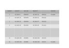
It's determined by the IP address you assign, thus:

Subnet-Table-1.jpg

We picked a split of 16 subnets each with 16 IP addresses and notice what the IP ranges are doing? Breaking on boundaries of 16 so, each time the IP address moves into the next block of 16 addresses, the value of the upper 4 bits of the last octet increases by 1. These 4 bits are in the area of interest to the subnet mask or, in other words, they indicate a change in the subnet number.

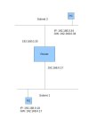
This indicates to the devices on the network that a given IP address is on the same subnet as itself or a different one. If you were to configure subnets 1 and 2 with a router between them, it would look something like this:

Subnet-Example-1.jpg

In the above example, the subnet mask (255.255.255.240) is the same irrespective of subnet and your gateway is always on your own subnet.

Behind the mask

Subnet masks can only take a few values (255.255.255.x assumed):

255.255.255.0 – a default
255.255.255.128 – equipment dependent, may not be usable, best avoided
255.255.255.192 – 2 usable subnets, 62 usable devices
255.255.255.224 – 6 usable subnets, 30 usable devices
255.255.255.240 – 14 usable subnets, 14 usable devices
255.255.255.248 – 30 usable subnets, 6 usable devices
255.255.255.252 – 62 usable subnets, 2 usable devices
255.255.255.254 – equipment dependent, may not be usable, best avoided
255.255.255.255 – a default, special case

Any other value is definitely invalid.
 
Back
Top