Circuit Board

Needs to be wire ended, surface mount pads have burnt away. Physically not much bigger than a 1N4148 (got plenty of others with higher rating).
Reg i/p draws 2.5ma on first, and 36ma on second. Think max rating for each is 100ma o/p (not clear from spec, says "in excess of 100ma", but no max quoted.
Not checked reg o/p circuitry yet, but without harness plugs connected, can't guess at working load. Will check for pcb bulbs, but if 100ma is max?


36v ok for regs, but pushing it for 35v caps, tractor pcb from 1998, modern lower voltage VDRs may be physically smaller?

Will try to post a pic, but the light angle is critical to read anything much.

Possibly were larger back then. Just been talking to a colleague who has messed around with things like this before and he said load dumping can cause voltages in the 20V region. So I think you might be looking for a varistor in the 27V~30V area.

How about a 1N4007 or 1N4004 diode, everyone has those lying about. There will be some inrush current.
 
@Spectre.... @dazling.......anyone else interested.

Attached is the pcb psu section "reverse engineering". Both regs working normally, but only one has o/p connections.
Current seems reasonable for onboard chips (42ma, reg max is 100ma), no excess heat anywhere.

Capture.JPG

Settled on a 25 vac (31 vdc) varistor, to keep the 35v caps happy, but upgraded to 26 joule, about the same diameter as the old one.
Can't get anything like it locally, so ordered one, should be here Wed or Thurs. Then will post back and cross fingers!:Biggrin2:

@dazling......PM your address when you get time.
 
Last edited by a moderator:
If you are getting more then one MOV then fitting two is also an option which will prolong their life if they are intermittently operating.
 
If you are getting more then one MOV then fitting two is also an option which will prolong their life if they are intermittently operating.

Good idea, never thought of that!

Better see if it works on the tractor first, if so dazling's got a little job.:Biggrin2:
 
Am I missing something here or is there something wrong with this circuit design?
The first regulator having no output connection may as well not be there, the capacitor on the output should be a minimum of 100uf to maintain stability. The regulator being an AT series will shutdown at pretty much anything >40v shortly after negating its' 60v load dumping feature thus protecting itself and its' load.
The MOV has a clamping voltage of 77v, the original kicked in and dropped to 7 ohms which gives a minimum of 11A current flowing through a 1A rated diode. We only know the clamping voltage but the actual input voltage may have been much higher.The heating time of the diode would be extremely short and obviously track damage would occur.

Spectre posted that his mate said load dumping can cause voltages in the 20V region, I have read that they can be in the region of 120v. Don't know about this though, automotive electronics wasn't my thing.
In Danforths' nicely reverse engineered circuit it shows 2 forward biased diodes in series, why bother? The input diode dies shortly after the MOV kicks in if overvoltage is sustained and current would no longer flow through the second diode as soon as the MOV kicked in anyway.
The MOV has a fast reaction time of around 4ns and will quickly react to shunt excess to ground. A fuse is slower and especially in this case you would opt for an anti-surge which should remain intact after the MOV had shunted transients/spikes and returned to its' normal operating voltage and open resistance status. If on the other hand the excess voltage wasn't due to transients/spikes and continued the fuse wire will melt and possibly shatter the glass but save the board and tracks. The diode if used instead, slower and obviously having heated externally with everything it is in contact with suffering damage.
The regulator outputs around 100ma so I would have been tempted to insert a fuse rated at 125ma anti-surge and as Spectre posted solder another MOV in parallel with the other.

I was only a repair engineer not design so clearly there is something I am missing here.

I'm no expert on automotive circuits but some of it might well be required for certification.

At a guess the first regulator will be connected to a power plane within the PCB stack.

I've seen some comedy designs before, to the extent where people have thought I've made a mistake when looking at competitor's designs.

The transient voltage produced by load dumping might well be higher but it might be of such short duration that there isn't enough energy in it to cause damage. The bloke I quizzed about the MOV wasn't a random chap but a colleague with a doctorate in electronic engineering and a few decades experience. For some reason, he's looked into this exact subject before (he seems to have looked into most things, so we all ask him) and he was happy with a ~30V MOV. I'd tend to believe him because I know his design history, especially in power supply.
 
Am I missing something here or is there something wrong with this circuit design?
The first regulator having no output connection may as well not be there, the capacitor on the output should be a minimum of 100uf to maintain stability. The regulator being an AT series will shutdown at pretty much anything >40v shortly after negating its' 60v load dumping feature thus protecting itself and its' load.
The MOV has a clamping voltage of 77v, the original kicked in and dropped to 7 ohms which gives a minimum of 11A current flowing through a 1A rated diode. We only know the clamping voltage but the actual input voltage may have been much higher.The heating time of the diode would be extremely short and obviously track damage would occur.

Spectre posted that his mate said load dumping can cause voltages in the 20V region, I have read that they can be in the region of 120v. Don't know about this though, automotive electronics wasn't my thing.
In Danforths' nicely reverse engineered circuit it shows 2 forward biased diodes in series, why bother? The input diode dies shortly after the MOV kicks in if overvoltage is sustained and current would no longer flow through the second diode as soon as the MOV kicked in anyway.
The MOV has a fast reaction time of around 4ns and will quickly react to shunt excess to ground. A fuse is slower and especially in this case you would opt for an anti-surge which should remain intact after the MOV had shunted transients/spikes and returned to its' normal operating voltage and open resistance status. If on the other hand the excess voltage wasn't due to transients/spikes and continued the fuse wire will melt and possibly shatter the glass but save the board and tracks. The diode if used instead, slower and obviously having heated externally with everything it is in contact with suffering damage.
The regulator outputs around 100ma so I would have been tempted to insert a fuse rated at 125ma anti-surge and as Spectre posted solder another MOV in parallel with the other.

I was only a repair engineer not design so clearly there is something I am missing here.

Don't think you're missing anything, didn't make much sense to me either, but we don't know what's plugged in externally.

I double checked the track layout before posting, so it's the only thing I'm certain about. The remains of the "frazzler" does have a band on it, and a diode is the only
polarized 2 pin, (series) component that I could think of. As you say, a fuse wouldn't have done the damage, but the original component had worked for around 15 years.
Without knowledge of the external circuitry, replacing like with "best guess" seemed the safest course (at least till we know whether the tractor works or not).

I can only assume the redundant reg is fitted to standardize pcb's across different models, link connected if needed, not used on this.
The caps across the reg o/p's are smd marked 47-10 K1, with 2 (inside a circle). They are polarized, now I've had another look, didn't seem important just for schematic,
so probably higher values.

As for MOV's, I've only ever changed them for original, or known equivalents, before now. I know the caps across the 12v supply from the "frazzler" are 35v max.
I'm assuming transients over 35v will damage them, so chose highest voltage MOV which should shunt under 35v ( 25vac, 31vdc, according to spec).
If you think a higher voltage MOV won't damage the caps, I'm open to suggestions.
 
Last edited:
Don't think you're missing anything, didn't make much sense to me either, but we don't know what's plugged in externally.

I double checked the track layout before posting, so it's the only thing I'm certain about. The remains of the "frazzler" does have a band on it, and a diode is the only
polarized 2 pin, (series) component that I could think of. As you say, a fuse wouldn't have done the damage, but the original component had worked for around 15 years.
Without knowledge of the external circuitry, replacing like with "best guess" seemed the safest course (at least till we know whether the tractor works or not).

I can only assume the redundant reg is fitted to standardize pcb's across different models, link connected if needed, not used on this.
The caps across the reg o/p's are smd marked 47-10 K1, with 2 (inside a circle). They are polarized, now I've had another look, didn't seem important just for schematic,
so probably higher values.

As for MOV's, I've only ever changed them for original, or known equivalents, before now. I know the caps across the 12v supply from the "frazzler" are 35v max.
I'm assuming transients over 35v will damage them, so chose highest voltage MOV which should shunt under 35v ( 25vac, 31vdc, according to spec).
If you think a higher voltage MOV won't damage the caps, I'm open to suggestions.

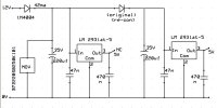
Is that regulator definitely connected to nowt? Have a look for vias near the output.
 
Is that regulator definitely connected to nowt? Have a look for vias near the output.

One only, through to comps fitted on the other side of the pcb, which are connected to socket pins.

Not plated through, never wire soldered, and still covered in lacquer.
 
Poor design, I'd always want multiple vias on a regulator :).

Perhaps it powers something that isn't present?
 
Poor design, I'd always want multiple vias on a regulator :).

Perhaps it powers something that isn't present?

Could be, but why not connect on pcb and alter wiring harness to suit? Can't get a free wiring schematic, to have more idea.

Still, it's never been connected outside the reg o/p track on the pcb, so not too concerned about it, got enough mysteries .:)

.
 
Am I missing something here or is there something wrong with this circuit design?
The first regulator having no output connection may as well not be there, the capacitor on the output should be a minimum of 100uf to maintain stability. The regulator being an AT series will shutdown at pretty much anything >40v shortly after negating its' 60v load dumping feature thus protecting itself and its' load.
The MOV has a clamping voltage of 77v, the original kicked in and dropped to 7 ohms which gives a minimum of 11A current flowing through a 1A rated diode. We only know the clamping voltage but the actual input voltage may have been much higher.The heating time of the diode would be extremely short and obviously track damage would occur.

Spectre posted that his mate said load dumping can cause voltages in the 20V region, I have read that they can be in the region of 120v. Don't know about this though, automotive electronics wasn't my thing.
In Danforths' nicely reverse engineered circuit it shows 2 forward biased diodes in series, why bother? The input diode dies shortly after the MOV kicks in if overvoltage is sustained and current would no longer flow through the second diode as soon as the MOV kicked in anyway.
The MOV has a fast reaction time of around 4ns and will quickly react to shunt excess to ground. A fuse is slower and especially in this case you would opt for an anti-surge which should remain intact after the MOV had shunted transients/spikes and returned to its' normal operating voltage and open resistance status. If on the other hand the excess voltage wasn't due to transients/spikes and continued the fuse wire will melt and possibly shatter the glass but save the board and tracks. The diode if used instead, slower and obviously having heated externally with everything it is in contact with suffering damage.
The regulator outputs around 100ma so I would have been tempted to insert a fuse rated at 125ma anti-surge and as Spectre posted solder another MOV in parallel with the other.

I was only a repair engineer not design so clearly there is something I am missing here.

@chookey

Don't want to risk further disturbance in the area (not much track is left except that inaccessible because of the socket).
I can't remove the socket because the pins are soldered on both sides of the board, but another burnout could make it unrepairable.

The addition of a fuse makes sense though, and would give some insurance. It could be external to the pcb, I can't see any other connecting
track off that particular 12v pin, except the one shown feeding the regs.

So, an "in line" type could be fitted in the wiring harness. It could easily be bridged again if preferred, and if it blows we know there's another
problem without any pcb damage.

@dazling .....are you up for it?:)
 
Last edited by a moderator:
yeah go for it I was lost 4 pages ago so will go with whatever is recommended in here
 
yeah I could prob do that easy enough lol
 
An update on the tractor saga:-

The owner has finally admitted that it was jump started on 24v, so that part of the mystery is cleared up.
The pcb was re-fitted with an inline fuse as suggested. The instruments work, the engine starts and runs OK.

Problems now:-

The auto transmission doesn't work (guessing ecu, or sensor damage somewhere).
It's got 8 gears (and half gears, whatever that means) and he's going to get a specialist for diagnostics.

Some sort of alarm remains when the engine is switched off, clears when the inline fuse is removed and replaced.
Another addition to my almost infinite "don't understand" list (remaining pcb fault, or elsewhere?).

Dazling says he will post the final outcome when known, just have to wait and see.
In the meantime, thank you all, for your contributions and suggestions. It's at least a half success.:THANKS:
 
as said i will post when or if there is ever a final outcome as danforth has said the the PCB ( dashboard ) was refitted and as far as i can tell works how it should
the only thing is the alarm sound that is not right but as already said when i take out the inline fuse it stops, i can replace the fuse and the alarm DOES NOT sound unless
i turn the ignition on and off again it seems that there maybe power still going to the pcb or enough to sound the mini speaker on the back of the pcb untill the fuse is pulled
therefore taking all power from the pcb.
It is strange that the fuse can be replaced instantly and the alarm stops? if it is the pcb then that wont be a problem because ill install a toggle switch to kill all power
but i do suspect that there is further damage weather this is going to be a simple fix or not i dont know but will post back any discoveries lol

Thanks everybody for there help and a Big thanks to Danforth for fixing the pcb
 
Seems to suggest then that the supply is not a switched one, but an always 12v supply. Removing and reconnecting the supply resetting the circuit. Probably also has an onboard rom with preloaded firmware that may be corrupt due to the burnup.
All guesses though, time for the experts.
 
Back
Top