Vu Solo Chip replacement advice

zomi

Inactive User
Joined
Oct 20, 2008
Messages
149
Reaction score
38
Just some general advice..

First and foremost you must be confident in your abilities..
Rushing and being not carefull will result in you damaging your box..
Please take that on board.
If you have doubt find someone dong repairs.. xbox/ phones to chip replacement level and get done..

Ok methods to repair..

Using hot air station
Set temp to about 360
heat around all legs..
with in about 1 min or so it will lift off.
To lift off get some tweezers
and very gently nudge the chip..
It will move easily when it is at temp...

here you can flux the pads and just hold the new chip in place and reheat

and it will line up when you apply heat abit fiddly but will work..


Or you can clean up the pads with solder wick..

line up the pins with the pads tack the ends
and solder each leg up.
dont forget to add flux...
and check the pins for shorts..


Also you may use solder paste
apply with syringe
then place chip
and start to heat up with hot air and it will
start to turn solid on the legs..

Most of the you tube vids make it look easy..
it not that easy if you cant solder..

If you are asking questions like is this ok
can i use this etc...
its not really for you.
I hope this helps.
 
Last edited:
Hi, any hot air station can recommend that is cheap

would this be ok


Thanks for the guide
 
Last edited by a moderator:
I've now had a chance to actually try a chip remove and replace on some old laptop memory sticks that I had lying around. The chips are smaller in length but the pin count is the same as the flash chip that needs to be replaced.

I didn't take actual pictures of the entire process as it's quite difficult to do unless you have an assistant which I don't :)

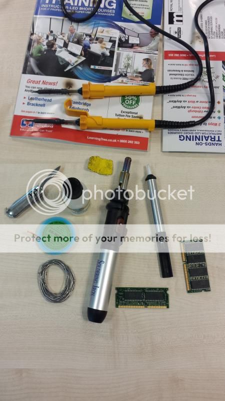
Shown below is the equipment I used:

20140508_141324_zps504d89ad.jpg


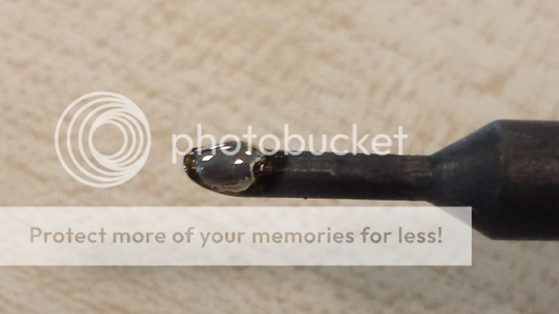
I had 2 electric solder irons, one with a standard tip and one with a fine point tip. I never actually needed to use the fine point tip iron in the end but I'd normally use that when removing bridges between legs and or for fine soldering. Important tip on the soldering irons is to keep the tips clean and tinned. Tinning just means to keep some solder on the tip, the tip should have a silver finish when wiped, if it goes black then give it a wipe as soldering is all about flowing and a black tipped soldering iron won't let the solder flow freely off on and off the tip. Pictures below show the 2 irons and the tip with solder.

20140508_141409_zpsa0125327.jpg


20140508_143345_zps7e93a6a0.jpg


Next in the first picture is a pen knife that I used when lifting one side of the chip, sand paper that I use to clean the tips of the soldering iron when cold, bottle of flux liquid, de-soldering copper braid, solder, gas powered soldering iron which has a catalyst function (more about this later), a de-soldering pump and 2 bits of laptop RAM. Now I do have other equipment but have chosen the above to show how to do it and that it can be done with what I've used.

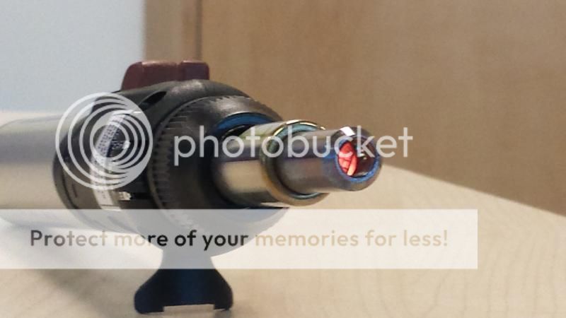
The gas powered soldering iron has a catalyst function, this means that it can act like a hot air soldering iron, can't accurately control the temps but it can blow either a naked flame or hot air as shown in the picture below:

20140508_141647_zpse905aaa6.jpg


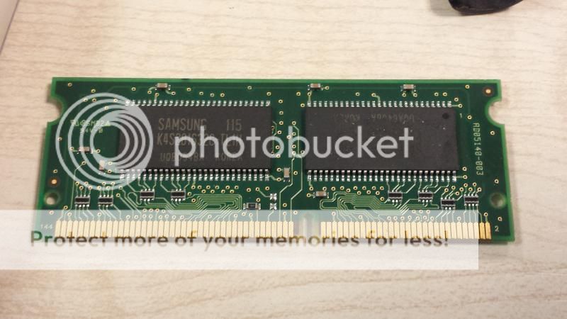
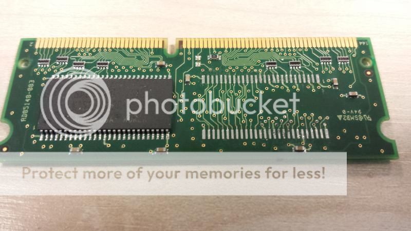
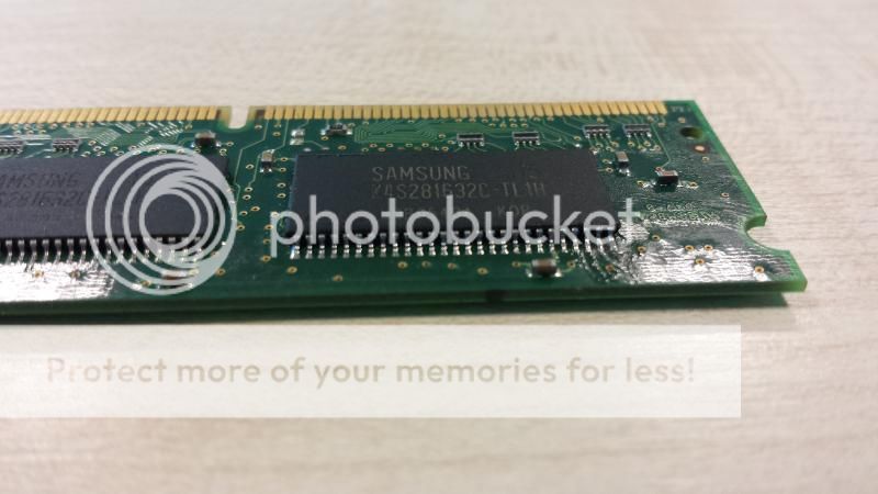
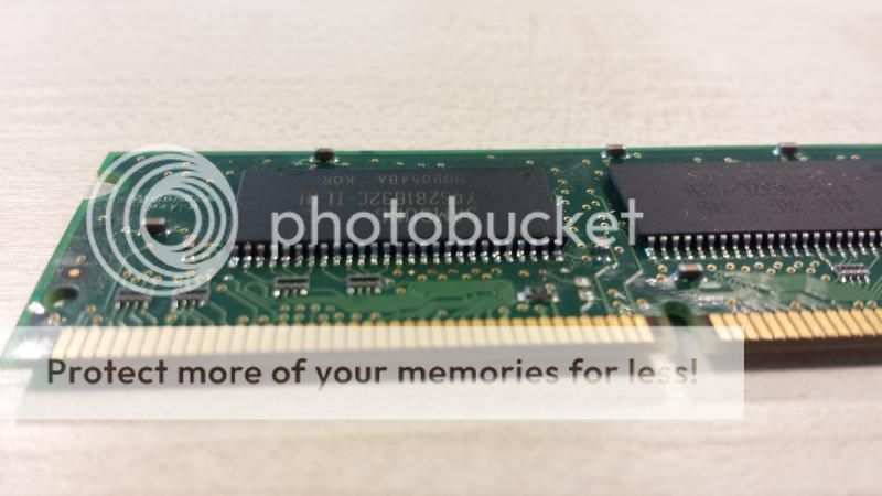
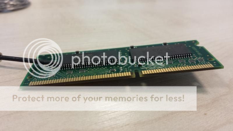
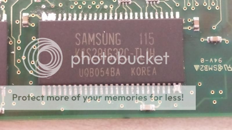
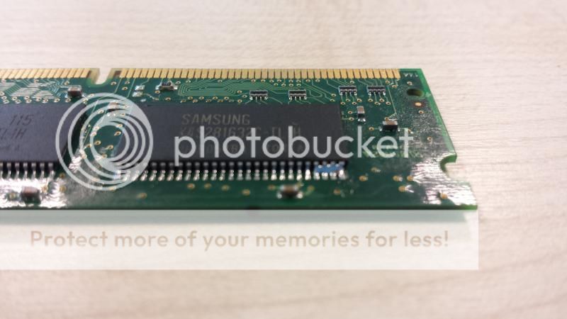
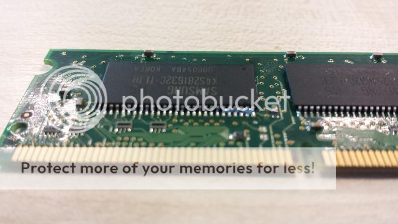
This is a close up of the memory stick that I'll be using:

20140508_141522_zps7d8480b1.jpg


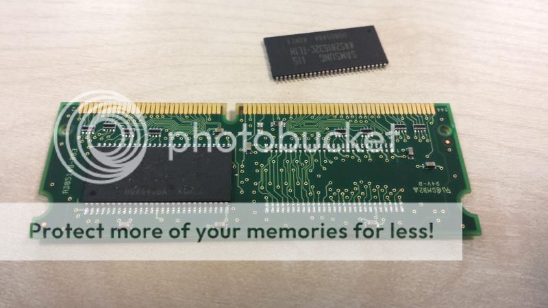
In order to remove the chip I first fluxed both sides of the chip, you don't strictly need to do this when removing but I did this to stop any tarnishing of the joints or legs whilst I had heat applied on the chip. I heated up one side of the chip gently going up and down the legs with the gas powered soldering iron; if you look closely you'll see the existing solder on the legs change colour, when this happened I used the penknife to gently lift up that side of the chip so that it clears the pads of the PCB. You have to be gentle, exert any force and you might end up ripping the pads/tracks off the PCB. Shown below is a picture of one side of the chip lifted. Again don't lift the chip too high off the board, remember that the other side is still soldered.

20140508_142238_zpsf3848057.jpg


Repeat this for the other side, again apply the heat, don't keep the heat in any one place for too long and when the solder appears to change colour lift off the other side. Here's a picture of the chip removed, you can just make out that the pads on the board have solder on then in peaks/bumps, now you can leave this as is but I used the de-soldering copper braid to remove the remaining solder off the pads and generally tidy up, this makes it much easier when aligning the replacement chip, bumpy pads and the chip won't sit properly and may move around.

20140508_142509_zps3afa6212.jpg


Again with the de-soldering copper braid, there should be no forced movement. I cut a piece of braid, put the end of the braid on the board and applied heat using the electric soldering iron with the flat tip until the solder melts and starts to flow then gently run the braid with the iron and heat applied up and down the pads mopping up the solder. If the braid gets stuck anywhere do not pull, apply heat to melt the solder and free it.
Here's a picture after I've cleaned the pads:

20140508_143124_zps198c8b77.jpg


You're now ready to replace the chip, at this point I put some flux onto the pads but you don't really need to at this point but the reason I did was so that the liquid flux would help to hold the chip in place once it had been aligned, I'm convinced it helps which is why I applied it. Once the chip is in place I then tacked it by soldering a couple of legs of the chip on opposite ends of the chip as shown in the picture below:

20140508_143724_zps1f0d65e0.jpg


I then reapplied the liquid flux to both sides, liquid flux is important as it stops the pads and legs from tarnishing which means the solder flows freely and it also helps to dissipate and distribute the heat. I then used the drag method of soldering, so I used the flat tipped electric soldering, cleaned the tip so that it was silver, applied the iron to the legs where I'd tacked, added some solder and then dragged the iron down the legs. Don't apply any more solder and keep dragging the iron down the legs, drag it in one direction only. There are plenty of videos on YouTube on this method so do a search and watch a video or 2. I then repeated this for the other side. I did end up with bridged legs so I applied some more flux and continued dragging the iron a few more times per side, if the bridges don't go then don't worry, for me both side still had bridged legs as shown below:

20140508_144204_zpsb7da4b2e.jpg


20140508_144146_zps1f1eb417.jpg


In order to remove the bridges you can either use the de-soldering copper braid to mop up excess solder or do what I did and use the de-soldering pump. Reason I chose the pump is that my soldering irons don't really get hot enough for easy use with the copper braid. For the pump, make sure the soldering iron tip is nice clean and silver, apply heat when the solder melts, use the pump to suck off the excess solder, repeat until all the bridges have been removed. I then once again applied liquid flux and then performed the drag on the legs on both sides but this time in alternate directions just to even out all the joints and solder.

You finally end up with this which is the chip soldered back in place:

20140508_144727_zpsac4f4930.jpg


20140508_144715_zps81c7c4d9.jpg


I am going to re-iterate what I've said before and that is that this isn't an easy task, you need the right equipment and you definitely need the liquid flux, some will say poo-poo but having the right equipment will make the job much more easier.

Any questions, if I've made a mistake or want more clarification then fire away.
 
Last edited:
VuSolo2 Chip Replacement Queries

Hi

Firstly, I know Zomi just put a thread up with some invaluable advice which I have used myself (http://www.digitalworldz.co.uk/vu-solo2-receivers-633/395344-vu-solo-chip-replacement.html)

I know Zomi said if your asking to many questions, you probably dont know what your doing but im sure a handful of people like me want to experiment and obtain the satisfaction of fixing it themselves or risking losing it all :p

So those who are willing to assist noobs, feel free to do so here.

I will tell you where im at, I have a hot air station, soldering kit and all tools, replacement samsung chip.

So far I have managed to take the faulty chip out using hot air blower - thanks to Zomi's instructions.

My difficulty is here, when putting chip back on. The replacement chip I placed on the pins/legs aligned, to the best of my ability, used hot air station hoping it will stick back on, left case open and powered it on, still got the whole dead/red lines on vfd display.

So does it have not soldered on?
Does aligning it with your hands and switching box on to see if alignment is sufficient not do the job?

Your advice will surely help me and hundreds of others.

Thanks
 
Didnt know this thread was open for discussion.

So here goes:

Hi

I know Zomi said if your asking to many questions, you probably dont know what your doing but im sure a handful of people like me want to experiment and obtain the satisfaction of fixing it themselves or risking losing it all :p

So those who are willing to assist noobs, feel free to do so here.

I will tell you where im at, I have a hot air station, soldering kit and all tools, replacement samsung chip.

So far I have managed to take the faulty chip out using hot air blower - thanks to Zomi's instructions.

My difficulty is here, when putting chip back on. The replacement chip I placed on the pins/legs aligned, to the best of my ability, used hot air station hoping it will stick back on, left case open and powered it on, still got the whole dead/red lines on vfd display.

So does it have not soldered on?
Does aligning it with your hands and switching box on to see if alignment is sufficient not do the job?

Your advice will surely help me and hundreds of others.

Thanks
 
I played around with just using heat to replace the chip and I personally found that most of the legs had dry joints. If you just want to use heat then you'd need to use liquid solder, put a thin line across the legs then use heat which will melt the solder.

Sent from my GT-I9505 using Tapatalk
 
Ok, so I took off the chip with ease, 10 second job.

Putting replacement on, nightmare.

So far I have tried just holding the chip in alignment with pins and legs, then I tried powering on the device holding in position and it doesnt boot up, basically acts dead, powers on, red lines on vfd display.

Then I looked at it, and the pins on the motherboard do seem rough, im guessing this is residue, thus the legs on the new chip are unable to conduct with the pins? - if so Im guessing I would need some solder wick to remove that residue, and then when I put the new chip in place, and align legs and pins, there will be clean conduct and device will boot up, or will I have to solder after aligning then it will boot up, or do I need to do something more for it to boot up?

Thanks.
 
If you've not cleaned the pads then the chip might not be sitting properly and therefore the legs may not be making proper contact, also if the chip moves whilst it's powered you risk other possible damage.

The red lines on the vfd is something I've not seen before.

As far as I'm concerned you've got 2 options, first is to drag solder the legs with a normal soldering iron or get some liquid solder, lay down a line and the heat with hot air.

Sent from my GT-I9505 using Tapatalk
 
has any used a local tv repair dude? how much do they charge?
 
Or just touch each leg with solder ..
I prefer to do that...
That way you know the joints are good.
Get the data sheet and just concentrate on the pins that are used...
A dry joint will result in the console not booting...
 
has any used a local tv repair dude? how much do they charge?

About £20. Finding is the hard part - I called ALL of my local satellite repair guys, mobile phone repair, xbox repair, they all seem to say TSOP chip replacement is too technical, they dont go in to that much depth. So good luck. P.S. Im in the London area.

Or just touch each leg with solder ..
I prefer to do that...
That way you know the joints are good.
Get the data sheet and just concentrate on the pins that are used...
A dry joint will result in the console not booting...

So basically its important to solder properly and make sure I use solder wick to clean pins, which do look like they have a bit of rough reside on them.

Now, I will solder one line, try to do it as neat as possible, so align pins with legs and solder both sides in one quick motion / line.

I should then power up device and it will work?

If even one pin is out of alignment im guessing it wont work which is frustrating considering how long it takes to align a pin - how those china guys managed to align the pins in 10 seconds I have no idea
 
If you've not cleaned the pads then the chip might not be sitting properly and therefore the legs may not be making proper contact, also if the chip moves whilst it's powered you risk other possible damage.

The red lines on the vfd is something I've not seen before.

As far as I'm concerned you've got 2 options, first is to drag solder the legs with a normal soldering iron or get some liquid solder, lay down a line and the heat with hot air.

Sent from my GT-I9505 using Tapatalk

When you say drag solder mate, you talking about using iron without any soldering tin? or doing it quick motion using soldering tin?
 
You align the chip in one go..
look down at chip and algin the corners then look to see all pins are lined up..
Magnify lamp helps.
Take the 4 corners down and then proceed to work on the legs...
all the points have to be soldered down for it to work..
Very surprised mobile/360 repair guys are turning you down..

They probably only repair the cracked iphone screens nowadays, thats enough to call someone a phone repairer. Unbelievable at how many people I called, literally typed it in on Google Maps and everyone just couldnt do it, most knew what TSOP chip replacement is, none knew or had equipment to do it.

Magnifying glass should definitely help.

Ill get solder wick, clean of residue on the pins, and solder it in.

Once done, I switch on box and it should just start up as normal, am I correct? or more needs to be done?
 
Solder..

Then if you are unsure about your sodlering check the pins with multimeter for shorts..

Esp the voltage and ground points each side..
Just check that little capacitor each side of the chip..
Should not be shorted..


You need to find people that do component level repairs...
 
I am using an antex 0.12mm solder tip on the iron, to resolder the chip.
Its only good for touching the legs of the chip.
Its too small for use with solder braid etc...
 
Use no clean flux.. saves on clean up afterwards.
 
Back
Top