VU+ Duo VU+ Duo Mini Clone Red Light

bootlegger

Inactive User
Joined
Mar 20, 2015
Messages
6
Reaction score
0
Location
isle of man
Hi all,
1st time poster here and looking for some help on a faulty Mini VU+ Duo Clone.
Having only just got into these things, I was a bit niaive when I bought a faulty one with the intention to repair it. I bought what i thought was an original and i bought a red light fix kit (cap replace) for it at the same time. When I received both items, I released the fix kit would not work. Turns out from what I gather is there is no such Mini version of the VU+ Duo, except for as a clones.

So I have a clone that has external power pack. It has power, and shows a red light on boot. The orange light appears when I use the remote. However the device appears dead.

I understand it may have been bricked by a VU software update that was sent out to kill clones.

So pondering things, my questions are;
1) What images can i use with this. Can I look at VU+ duo images, or am I reading right that it should be icloud box images?
2) Do I steer clear of original VU+ images - if I need clone image, where do I get them?
3) I understand you can use putty on the RS232 to examine on a PC the console out from when the box boots, but;
How do i connect the box up to my pc? I received some RS232 dongle device with the box, but I have no way of connecting it. What is it for? It would appear I would need 2 null modem cables to be able to connect to it - is this correct?
4) From what I read, I should only use old images that do not contain the brick code, but how do you stop the device rebricking itself - arent the updates automatic?
5) What is the recommended image for this device - what recommendations do people have? What is the stock image (probably best to try to recover that first if its available anywhere for download)
6) Is this even really recoverable. From the scare stories I have read, the brick code wipes the boot part of the FPGA and puts it in read only mode(?) so you can only reprogram it with an BSS(?) application. I have examined the internals and there does not appear to be a JTAG connector for reprogramming the chip as an alternative method that I have also seen mentioned. Is my only hope via RS232 and USB?

Help me OBI-WAN, you are my only hope...!

Thanks in advance for any assistance - I am sure I will no doubt have more questions once I have a few answers

Jason
 
I know this is an old post but thought I may be able to offer a bit more info that may help others with this same box.
I´ve acquired 3 of these now, and all with this exact same fault.
In my case I´m sure it´s nothing to do with the Nand being bricked but more to do with the "Security chip" or maybe the tuners.

My symptoms are exactly as those above, but if I monitor the Serial port I can see the box is accepting Images just fine, but refuses to boot to the splash screen.

At the point you would expect to see the splash screen the Kernel goes into "Kernel Panic, reboot in 180 seconds" and the box freezes (at this stage a working box would initiate the tuners)

After trying 20+ images I was able to find one PLI image that installs and boots just fine, but with the major problem that the tuners don´t work. (always displaying tuner fail, (although there is a 13v -18v output at the f connector)

I´ve tried to find a security chip update for this box but with no success (although it is supplied with the usual RS232 daughter board) I´ve tried the Ferrari update but get no response from the software on any of my boxes. (another reason I expect a security chip fault)

I´ve come to the conclusion it´s either a faulty security chip not allowing tuner initialization, or a faulty tuner.

If anybody has any further ideas I would love to hear them.

P.S. i did JTAG one of the boxes and it accepted the new flash file with no issues.


Dave.
 
Last edited:
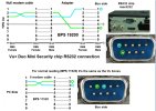
When connecting to the security chip these boxes use pins 1 and 6 unlike the vu duo 3 and 4.

Pin 2 on the pc side goes to pin 1 on the box and pin 3 on the pc side goes to pin 6 on the box. Pin 5 goes to pin 5.

If you use hyperterminal use baud rate 19200 this should give you an output if the security chip is ok. If you do get an output try flash same as vu duo it uses the same software.

- - - Updated - - -

Online Shop 10PCS STM8S103K3U6 ST8S103K3 8S103K3 QFN32 Original authentic and new Free Shipping IC|Aliexpress Mobile

This is the security chip in the vu duo mini if you need one
 
When connecting to the security chip these boxes use pins 1 and 6 unlike the vu duo 3 and 4.

Pin 2 on the pc side goes to pin 1 on the box and pin 3 on the pc side goes to pin 6 on the box. Pin 5 goes to pin 5.

If you use hyperterminal use baud rate 19200 this should give you an output if the security chip is ok. If you do get an output try flash same as vu duo it uses the same software.


- - - Updated - - -

Online Shop 10PCS STM8S103K3U6 ST8S103K3 8S103K3 QFN32 Original authentic and new Free Shipping IC|Aliexpress Mobile

This is the security chip in the vu duo mini if you need one

Thanks for this info, I did discover the pin assignments used but didn't realize i could use putty to check the chips output. I can see more testing on the horizon!!

also thanks for the link, it looks like a hard package to try and re-solder, i think solder paste and hot air rework may be the way to go here?

and just to clarify, are you saying i can use the normal VU Duo V3.2 loader and software?

Just to clarify, this is what I´ve been using

Mini-vuduo-Rs232 Working.jpg

Would this be OK, it looks like the board will accept it, and fitting would be easier.
Buy Products Online from China Wholesalers at Aliexpress.com
T, I, A, Dave.
 
Last edited:
Hi with the pinout corrected on the rs232 you should get a output on putty and the vu duo 3.2 loader will work. You can try this if you have a working box. If the chip is not giving an output it will need replacing.

The link you sent is a different socket to the one I linked so will not fit. Only a rework station with hot air or a heatgun will remove the chip.

- - - Updated - - -

The socket you need is QFN32
 
Thanks Mate, so i still need to reverse pins 1 and 6?
and I´ll have to check i get an output from pins 2 and 3 using a standard Null Modem Cable.
Just to check the Max3232 chip is still functioning, as if that has failed writing to the STM8S103
will be impossible anyway.
 
I have 5 mini duo´s here all with the same fault, tried listening with putty and had no response at all.
I even reversed pin 1 and 6 at the box to be sure.
4 of the 5 output the usual info to my null modem cable (1 just outputs garbage, so possibly a faulty max 3232 there)
I think I may order a few [FONT=&quot]STM8S103´s to try, there not expensive, and will update in a month or so[/FONT]
 
Hi mate, the 5 boxes you have do they all have the red light? Have you jtagged them yet.

After the jtag flash openpli it should boot then if you get tune failed the security chip has failed.

- - - Updated - - -

Also have you got any other vu type clones? you could possibly use them to revive the security chip.
 
all boot with pli, all output serial data, with other images on they all stop showing kernel panic restarting in 180 seconds. I did jtag one, it accepted the flash fine but no change.

I´ve ordered a few S103´s, Will update in 6 weeks or so when they arrive.

Thanks, brianmullen8
 
Only a full size vu solo clone (unsure if it´s a v2 or V3 will check later) stuck on red light, jtagging reports bad block at 0 so probably a new nand chip will sort it.
I received a new [FONT=&quot]K9F1G08U0A by post today so will probably have a play with that tomorrow.
If that fails, i may look at the security chip it uses.[/FONT]
 
I got past the bad block issue a few times give this a try

When it says bad block power off the box then power back on

Keep pressing refresh until the chip is found and press flash.
 
I did try a few times, but have now changed the nand and all is fine.
Thanks anyway.

P.S. I´ve just read your post about Duo Security Chip Repair, Very Interesting...
 
Does renewares work on the solo, you could install the security chip into the solo and flash.
 
I was going to try that if the nand swap failed but as it´s a friends´box, i´ll just wait till my new chips arrive and try then.
 
brianmullen8 I do have a couple of working V3 duo´s, actually there branded as Max Duo´s using the standard V3 security board, are you suggesting i could put the mini duo´s security chip into that to try flashing?
I know they both use a different chip but may be compatible.
 
Hi Dave, if you get the adapter board I posted earlier you can solder the individual pins to the board then use the renewares to write the flash.
 
Yes good plan, I wish I had a spare Duo RS232 board as would be nice to try externally as others have done, may even look into building one
Would this be the correct pinouts for the [FONT=&quot]STM8S103 [/FONT]QFN32 Package?

pinout´s.jpg
 
Last edited:
s-l1600.jpg
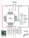
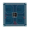
use one of these boards as your test board, install one of your stm8 and crystal onto the board you can then use this like a vu v3 clone chip.

on the reverse of the board you can also install a syncmos chip
 
Last edited:
Do we need the 2 Capacitors, 1 from each pin of the Xtal, dropping to the ground pin?
and if so do you know there value, (when programming an Atmega [FONT=&quot]18-22 picofarad capacitors would be used)[/FONT]
Can you confirm the crystal frequency (i´ve seen images with 30.000 and others with 22.1184 used)
 
Back
Top