
You are using an out of date browser. It may not display this or other websites correctly.
You should upgrade or use an alternative browser.
You should upgrade or use an alternative browser.
VU+ Duo capacitor change
- Thread starter boab34
- Start date
topchippyles
DW Member ++
- Joined
- Apr 11, 2014
- Messages
- 277
- Reaction score
- 158
Bit more info please
A capacitor is a device used to store an electric chargeBit more info please
Change in this instance means replace.

- Joined
- Aug 2, 2007
- Messages
- 5,413
- Reaction score
- 7,025
Capacitor failure is one of the easiest to fix that's if you can locate the offending item.
Normally there the barrel shape surface mount ones. Look at the top of it and if its bulging upwards then that's the bugger.
Flip the board out get some solder wick, solder, smallish soldering iron and remove it.
Look at the writing and buy a new one exact same (eBay easiest to get it right) drop it in making sure you get post/neg right way then solder away.
Wiggle the excess wire or nail clippers all done .
Takes 20 minutes tops
CPC, Farnell, RS Components or ebay
First hit I got for RS Components

Thought I'd seen it all, lol. Just flick them off with a hot iron mate and replace with proper 105° 220uf 16v caps
Sometimes when those capacitors go, the regulators go too. And as mentioned on other forum, it could also be PSU. Not worth throwing money at it unless you know what component is faulty or you can test with a donor part. Not to sure what the voltages are, but I'd test using a PSU for a PC if the voltages are the same.
I wouldnt't buy a second hand duo unless it is dead cheap, there are more powerful receivers out there.
I wouldnt't buy a second hand duo unless it is dead cheap, there are more powerful receivers out there.
Thought I'd seen it all, lol. Just flick them off with a hot iron mate and replace with proper 105° 220uf 16v caps
lack of pull-through on their THT soldering is more shocking
") .
.Panel breakoffs still left on their mouse bites.
I wonder if they got the Dc-DC converter design wrong and it puts out too much ripple, killing electrolytics. Not seen a 220uF ceramic in that package as far as I remember.
Last edited:
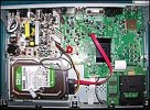
Yes, I was surprised by the panel breakoffs as well. Not worked on one of these boxes but I assume they originally had 85°C electrolytics which dried out. Larger cap of the 2 top right of the pic appears to be an 85°
Yes, I was surprised by the panel breakoffs as well. Not worked on one of these boxes but I assume they originally had 85°C electrolytics which dried out. Larger cap of the 2 top right of the pic appears to be an 85°
Where did the find them, I thought they were all 105C now.
Above I meant to say "220uF ceramic" in that package, edited. Might be able to fix it with some ceramic filtering capacitors but keep the electrolytic.
Similar threads
- Replies
- 0
- Views
- 156