Alternative energy

trevortron

VIP Member
VIP Member
Premium Member
Joined
Feb 20, 2013
Messages
3,033
Reaction score
3,905
Location
Somewhere else
I am lucky enough to live in a pleasant climate and for a number of years I have toyed with installing PV (electric) solar panels.
There used to be a sell-back system here, but the few licences were quickly handed out to friends & families of the issuing entity, as is the way here. (Not complaining, it was like this long before I got here and I accept as-is!).
However, it still makes sense I think to generate power for ones own use. By using that, it should slow down or stop the electricity meter thus reducing the bill.
To have a system installed professionally would never make economic sense. The many snouts in the trough would push the cost up to the point where it would never pay for itself. But reasonably priced systems can be bought and, with some DIY skills should be a doddle to install.
So I have some available roof space (will have more soon once I re-locate the various satellite dishes dotted about the place) with good clear views to the south. (This is my neighbour's roof- to the south- nice and un-cluttered- there is more flat area to the left, out of frame).

vs.jpg

My first thought was how to align the panels. Due south is the norm of course, but it seems very wasteful, as the early morning and late evening hours would be lost, as solar panels only work well when facing the sun. So this is where the whole project became a bit more complicated.
I decided to make a tracking system. I have installed numerous motorised satellite dishes over the years and decided to adopt a similar system to that of a prime focus (polar mount)dish, only with dual-axis (EL and AZ) control. I also have skip-loads of old (and some unused but redundant) kit lying around, so I will be using as much of that as I can. My thinking is that by having the pivot perpendicular to the sun's arc, the elevation motor would have very little work to do on a daily basis, its only function would be to adjust the elevation seasonally. (A quick calculation with the help of Google reveals that the elevations for 37°N are roughly 30° and 60° for summer and winter respectively).
So the kit I already have to hand: Three satellite dish "jacks"- old Echostar 18" ones that still work well. Designed for 36V but run quite happily on 12V- Numerous 80mm galvanized dish brackets with associated hardware- Boxes and boxes of screws, nuts, washers (I don't throw much away!) and hopefully most of the tools I will need.
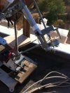
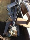
Prior to spending a four-figure sum on the panels, inverters etc., I thought it would be an idea to throw together a working model- albeit single-axis. I had a couple of old 5 watt panels powering a bathroom fan, so I made up a rudimentary base (backplate off an old sat dish) and using some threaded dowel and a motor (and gears) robbed from an Airwick room smellifier (PIR already robbed for something else!) all I needed was a control circuit to run the motor to keep the panels facing the sun. I cheated a bit at this point- I had a quick look on the 'Bay to see if I could glean (OK, steal!) some ideas, and found a ready-made unit for less than £20. At that price it hardly seemed worth switching on the soldering iron. It arrived amazingly quickly considering it came from Malaysia (or wherever) and, although it was far from perfect, with a couple of modifications, it soon provided the necessary.
So the baby unit was born and after a couple of teething problems it is now working away, faithfully tracking the sun from about 9am (it takes about an hour to realise that the sun's behind it first thing!) until sun-down. I will post some photo's of it in the next post.
 
Last edited:
Impressive mate, I have a level 3 in solar PV design installation .

Shading is critical to solar PV, if you shade just one cell and there maybe 70+ on one panel you create a reverse current which in turns creates a load...

Temporary shading (leaf etc) is ok, but long term shading (aerial, trees, buildings is very bad). If you have any permanent shading it can ruin returns and outputs.

If you have shading, it's best to use optimisers on the panels they will switch off the output of the panel with the shading this allows the other modules to output optimum performance and not send reverse current to the bad load (shaded panel).

Trackers are great, especially in winter months they can increase winter months by up to 300%.

The best form of solar for hot climates is thermal though with a small pump and well insulated special solar cylinders - one hot day can heat your hot water for days, Solar PV is great though.

What are your string outputs VOC and ISC for the panels you are installing?

Are you using batteries for night time?

Sounds great, more pics please matey.
 
Wow. Great to know you know your stuff @Mick! I always wondered what your 'day job' was lol!!

Shading should not be a problem. Ignore the chimney, the array will be going to the left of that and quite a bit behind, so even with the low winter sun it shouldn't be an issue.
As it happens I was planning to wire all the panels in parallel. They are sets of four 12V (up to 18V) panels and come bundled with grid-tie inverters. I assume each panel will have a blocking diode- but I will be checking now.
I've read the claims about trackers, and, wondering if they are true or hyped-up sales talk, I am planning on doing my own experiment. I'm having two identical 600W arrays- one static and one tracking- and see how they compare. When you say the yield is notably better in winter, I take it they hunt around for the best light among the clouds?
I already have a water heating panel. Panel on roof- 1M X 2M (45° elevation) and tank, pump & control panel inside. It provides adequate hot water for the two of us for around 11 months of the year. Two or three consecutive cloudy days & the gas boiler has to burn off some cobwebs. But as you say, one decent day & it's back up again.
Re. the panels' specs-

Related power: 160W
Maximum/Peak Voltage(Vmp): 22.41V
Open Circuit Voltage(Voc): 17.9V
Maximum/Peak Current(Imp): 9.87A
Short circuit current (Isc): 8.89A
Size: 1452x665x35 mm

Here are some pic's of my 'lash-up'.

photo 1.JPG

Pic taken from the south side of the panel, late pm. By sunset it'll appear vertical.


Last edited:
Wow. Great to know you know your stuff @Mick! I always wondered what your 'day job' was lol!!

Shading should not be a problem. Ignore the chimney, the array will be going to the left of that and quite a bit behind, so even with the low winter sun it shouldn't be an issue.
As it happens I was planning to wire all the panels in parallel. They are sets of four 12V (up to 18V) panels and come bundled with grid-tie inverters. I assume each panel will have a blocking diode- but I will be checking now.
I've read the claims about trackers, and, wondering if they are true or hyped-up sales talk, I am planning on doing my own experiment. I'm having two identical 600W arrays- one static and one tracking- and see how they compare. When you say the yield is notably better in winter, I take it they hunt around for the best light among the clouds?
I already have a water heating panel. Panel on roof- 1M X 2M (45° elevation) and tank, pump & control panel inside. It provides adequate hot water for the two of us for around 11 months of the year. Two or three consecutive cloudy days & the gas boiler has to burn off some cobwebs. But as you say, one decent day & it's back up again.
Re. the panels' specs-

Related power: 160W
Maximum/Peak Voltage(Vmp): 22.41V
Open Circuit Voltage(Voc): 17.9V
Maximum/Peak Current(Imp): 9.87A
Short circuit current (Isc): 8.89A
Size: 1452x665x35 mm

Here are some pic's of my 'lash-up'.

View attachment 91264

Pic taken from the south side of the panel, late pm. By sunset it'll appear vertical.


I don't install solar :) - it would seem I just love courses, well that is what my Mrs tells me and it does cost quite allot - training!

To be honest, I am fascinated by green technology... we will be sooner or later buying a home in either Portugal, Spain or the south of France. And it will be running mainly from green technology, it must have a grid connection but I would like to take advantage of the suns irradiation.


Remember the lower the power (12v) the bigger your cable needs to be sized!!!!

From your panel specs you posted you will potentially be sending 36A down it in parallel at 18v

Now that at 18v will need a huge cable!! Personally I would be putting that in series and using an inverter that can handle 72v.

This is a good website to work out cable calcs:
https://www.tlc-direct.co.uk/Technical/Charts/VoltageDrop.html

However I think you want this to charge batteries right, My knowledge on this is limited as I never studied this part of solar as we only grid supply over here (normally) in the UK.

In parallel you make an addition to the amps, in series you make an addition to the voltage.

You will also need to know your countries STC (standard test conditions) so you can make adjustments to tweak your system.

(UK STC = Temp 25 / Irradiation 1000 / air mass 1.5) you will need to find out Portugal's STC

ISC Irradiation adjustment: Irradiation on the day divided by 1000 times by ISC
The figure you are left with is your adjusted ISC

VOC Temperature Adjustment: (slightly more tricky)

STC Temperature take away OR add actual temperature on the day

Temperature Difference (from above calc) times by (VOC times by Coefficient of panel)

Then depending on the actual temperature of the day reading you either add or take away from the last calculation, so if your temperature was 40 on the day but the STC temp in Portugal is 30 you would take away. if the Temperature on the day was 18 and the STC in Portugal is 30 you would ADD.

STC VOC minus OR add above calculated figure
The figure you are left with is your Adjusted ISC


I know that lot sounds like brain damage but these are really important calculations and will not only help you determine that your panels are working correctly but they can be then used to calculate potential outputs and gains etc.

Be careful with the cable size you might need for the panels and also the volt drop (our maximum is 3% in the UK on the DC side and 1% on the AC for photovoltiac)

But looks great mate - well done.

Mick
 
Last edited:
I intended posting more pic's but my browser froze and I wasn't going to re-write the post AGAIN lol!

I fully understand what you are saying about the series/parallel differences (power line transmission theory in the old money) but happily the LT cables will be very short so hopefully losses there will be minimal. I wasn't intending having batteries, it was really just to slow down or stop the meter during the day. I'm on a dual-rate tariff so night time (metered) usage is half price.

I must admit I was reading the STC, adjusted ISC and VOC calculation formulae and wondered how this would be applicable in my case. For instance what adjustments can be made to tweak the system for peak performance once the STC is known? I can certainly see its value on a large scale system, especially if investors are involved. They love numbers!

Getting back to my "toy", here is a close-up of the £20 LED-based motor control unit.

photo 2.JPG

Here are some of the back end: Here you can see the Airwick motor and gear assembly which I managed to attach to a length of M8 threaded dowel. When this rotates in the long nut at the top it causes the panel assembly to swivel one way or the other- depending on where the strongest light is.

photo 3.JPG


photo 4.JPG


Here you can see more clearly how the rotating dowel swivels the panel assembly.

photo 5.JPG


With the exception of the motor controller, this is made up entirely of bits & pieces I had lying around my garage. Aerial brackets, a bit of an old TV wall bracket, the remains of a satellite dish (or two)- even the afterthought thrust relief (seen here just above the motor, fitted after it pulled itself apart) is a discarded casing off a DiSEqC switch. The aerial bracket you can just see at the far end is counterbalance, the 12V battery is out of a UPS and as well as providing power for the motor, also acts as good ballast to stop the whole thing blowing over.

The shadow on the right is deliberate. It shades the sensor just as the sun is setting, so the panels head off eastwards looking for more light. That way they are ready for the morning.
 

Attachments

  • photo 4.JPG
    photo 4.JPG
    21.4 KB · Views: 61
  • photo 5.JPG
    photo 5.JPG
    20.1 KB · Views: 61
The measurements will allow you to know if your panels are operating correctly, efficiently.

Love the way you have built it out of allot of items laying about. Very clever
 
Love the way you have built it out of allot of items laying about. Very clever

Well it may surprise you (not!) that I am hoping to do much the same thing with the finished article.
Since Astra 2 E, F & G "stole" most of our free UK telly, there's loads of redundant satellite kit going cheap or free. The 1.4 & 1.8m dishes had pretty hefty mountings. So far the only thing I know I will need to have made up is the main support beam- a couple of metres of 80 or 90mm galv. box section.
Talking of which- did your studies look into wind loading of these things? It does worry me slightly that 4m² in an upright position (sunset & dawn) will act as quite a sail. I'm satisfied the brackets I have in mind will stand up to sheer wind force, but whether they'll survive the torsional effects of helicals is a bit of a concern. Basically the whole array will be supported on one 80mm pole; the elevation jack won't provide any rotational resistance. (Thinks- if I had two in a triangle formation they could.....)
 
I have nothing to contribute but im very impressed and great reading. Now thats DIY :)unfortunately in scotland we are lacking in sun, however wind power is very much in full swing here.
 
I have nothing to contribute but im very impressed and great reading. Now thats DIY :)unfortunately in scotland we are lacking in sun, however wind power is very much in full swing here.

I know more than enough about the Scottish weather- it pretty much explains how I ended up here! (Ex-Edinburgh)
But funny you should mention wind power- I have also made a small wind turbine- again pretty much from scrap bits & bobs. Unfortunately we had some fairly serious wind the other day and it sort of had a wee accident. Long story, I'll start another thread with the gory details.
 
OK, things have moved on somewhat since the last post.

The "toy" tracking panel I made earlier has worked really well. I used it to power a small extraction fan in a bathroom that has no windows. The panel faithfully tracked the sun every day, even when the weather wasn't too good it 'hunted' to find the best light.

After a bit of thinking, I decided I didn't need to have anything fabricated after all for the big one.

The base was made from two 80mm dia. satellite dish wall-mounts- one 'L'-type, and one traditional 3-point one. They're made of pretty hefty galvanised steel and should last a good number of years.

Next I decided to make the moving part of the frame from galv. steel pipe. It is easy to get (though not cheap) but, essentially, it is easy to work with. And again, it should easily out-live the life of the the panels.

20151104_101525.jpg
This is it half-assembled in my workshop. You can see the E/W tilting motor on the right. The elevation motor isn't attached yet. At the very top you can just see the sensor for the tracking electronics.

20151104_101657.jpg

Here is a close-up of the two pivots. The lower joint is the remains of my old 1.4m prime focus dish. It supports the raising and lowering of the whole mechanism, to allow for seasonal changes in the sun's height in the sky. The upper part is the 'daily' E/W part- east in the morning, tracking through roughly 140° to west in the evening. Drive is provided by an old satellite dish actuator (or jack) and it is connected to the rotating pole using a simple (but strong) aerial bracket. The elevation motor (another jack) is attached now.

20151108_170245.jpg

This is the almost-complete unit up on the roof. I decided to fit two jacks for the elevation part. Not for additional strength, these things are incredibly powerful, but to provide more E/W stability/less strain on the main pivot in high winds. The two jacks effectively form a triangle thus reducing torsional strain lower down.

20151108_170308.jpg

Another shot of the almost-complete unit, with a few tools scattered about to give an idea of size.


20151111_165425.jpg

Panels on now. I had originally intended installing the two top panels horizontally (forming a sort of T) but in the end decided to do it like this.
It's around 5pm (hence the steep angle) with only about 1/2 hour of daylight left. And a LOT of mosquitos.

20151111_173722.jpg

This is a couple of minutes later, facing south. The round thing you see sticking out the back is an old (heavy) transformer I used as a counter-balance. The E/W motor toils a bit at the extremities.

20151111_173809_Richtone(HDR).jpg

Again, just before sunset. Here you can see the micro-inverter just to the left of the centre-cross. (The original 'toy' one can be seen in the background to the left- still working but minus the tracking now). The panel to the right in the background is for hot water.

Once the sun sets, the whole thing goes into sleep mode. The E/W motor parks the panel roughly horizontal, and the elevation comes right down as low as it can go- simply to reduce its vulnerability to wind through the night.

So I finally plugged the whole thing in the other day- and it looks like I will have to get in touch with the electricity board- it sent my meter FORWARDS!! Luckily I'd been warned of this possibility so I knew to check for it.

It is a 600W system, and I bought two. The other one will be somewhat less adventurous, with just an elevation adjustment (for seasonal changes), but no daily tracking. The idea is to compare the outputs from the two systems to see if it is really worth going to all the hassle of having tracking. I suspect the difference will be quite noticeable. Whether it would be financially viable is a different matter of course. All told this contraption only cost me a couple of hundred quid (excluding the panels) but of course I had a lot of the materials lying around. Oh, and probably at least as many hours!

I will report back with my findings.
 
Back
Top